Our mobile Internet Service Provider (ISP) has a bundle where they provide a 4G modem for internet access, and a separate TV set-top box that can be used to watch their TV content or to watch streaming services. This device was sent to us as part of the bundle, but at Zeus, we don’t really have a use for it: we don’t really watch television in our space. What we do have a need for, however, are low-power computers that can run Linux. In this blog post, we will hack this set-top box to run Linux instead of Android TV.
The constraints we lay out for this project are that the box must be easily turned back into running the original software again (in theory, we might be asked to give this device back. In practice, these devices are written off as soon as they’re sent to customers). This means that we cannot do any destructive inspection/testing and that we cannot overwrite important parts of the on-device storage. We would also like to get the most important hardware of the box working: Ethernet and HDMI.
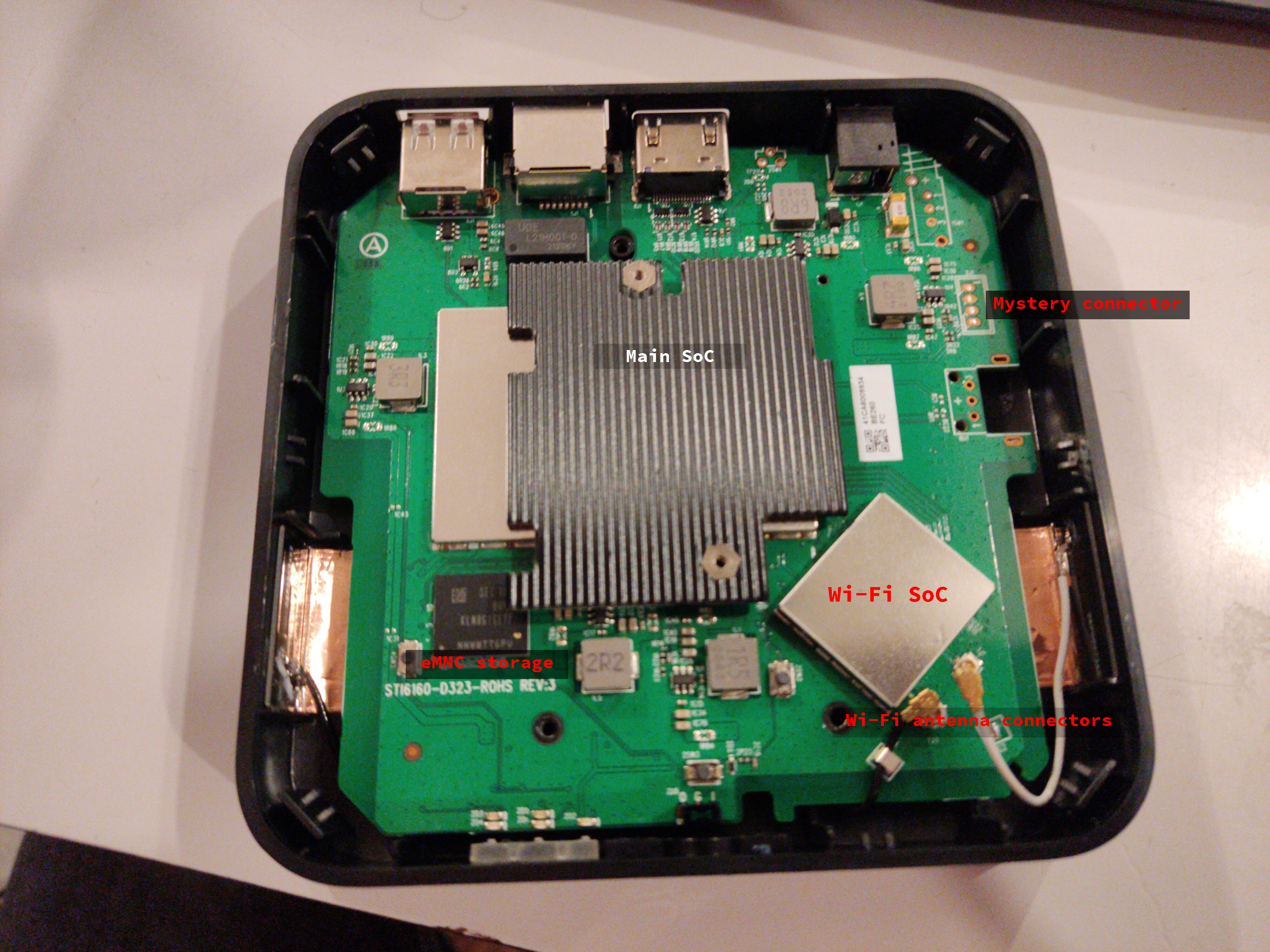
Our set-top box has an Ethernet port, a USB port, a barrel jack socket for power and an HDMI socket for video. It also has an IR sensor for the remote and several status leds. Looking up the label on the back of the set-top box, we found the website of the original vendor. It’s clear that this is a bit like a white-label product: the ISP buys the boxes from the vendor, adds their own branding/apps and then passes on these boxes to their customers. After doing a bit more research, it appeared that nobody had yet tried to put a different operating system on these boxes: we had our work cut out for us.
After opening up the box, we inspected the printed circuit board (PCB) marked as STI6160-D323-ROHS in the device. Unfortunately, most of the interesting chips are under an aluminium RF shield, making identification of what chips it uses harder. One chip that is visible is marked as KLM8G1GETF. This is apparently an eMMC storage chip, made by Samsung. Getting the data stored on it would be very nice to get more information about how to proceed. We identified two possibilities for doing this:
- Desoldering the eMMC chip, soldering it on another PCB and reading it out from there. I personally have some experience with this from a workshop at the HITB conference, so this seemed possible. However, since the eMMC chip has a BGA footprint (ball grid array: the bottom of the chip has very small solder balls that connect it to the PCB) this is very hard to do and has a high chance of failing, which would destroy the device.
- Soldering wires to the PCB itself, tapping into traces that are used by the chip. Only 5 wires would need to be soldered, but identifying where to solder them to proved to be rather hard. A technique that is used for this, is overlaying a picture of the pinout of the chip on a photo of the PCB. Unfortunately, even with this, we were unable to find the correct PCB traces.
Both approaches turned out to be hard, so dumping the flash at this point was not viable. Luckily, we also identified a suspicious unpopulated 4 pin header, which could potentially be a debug port.
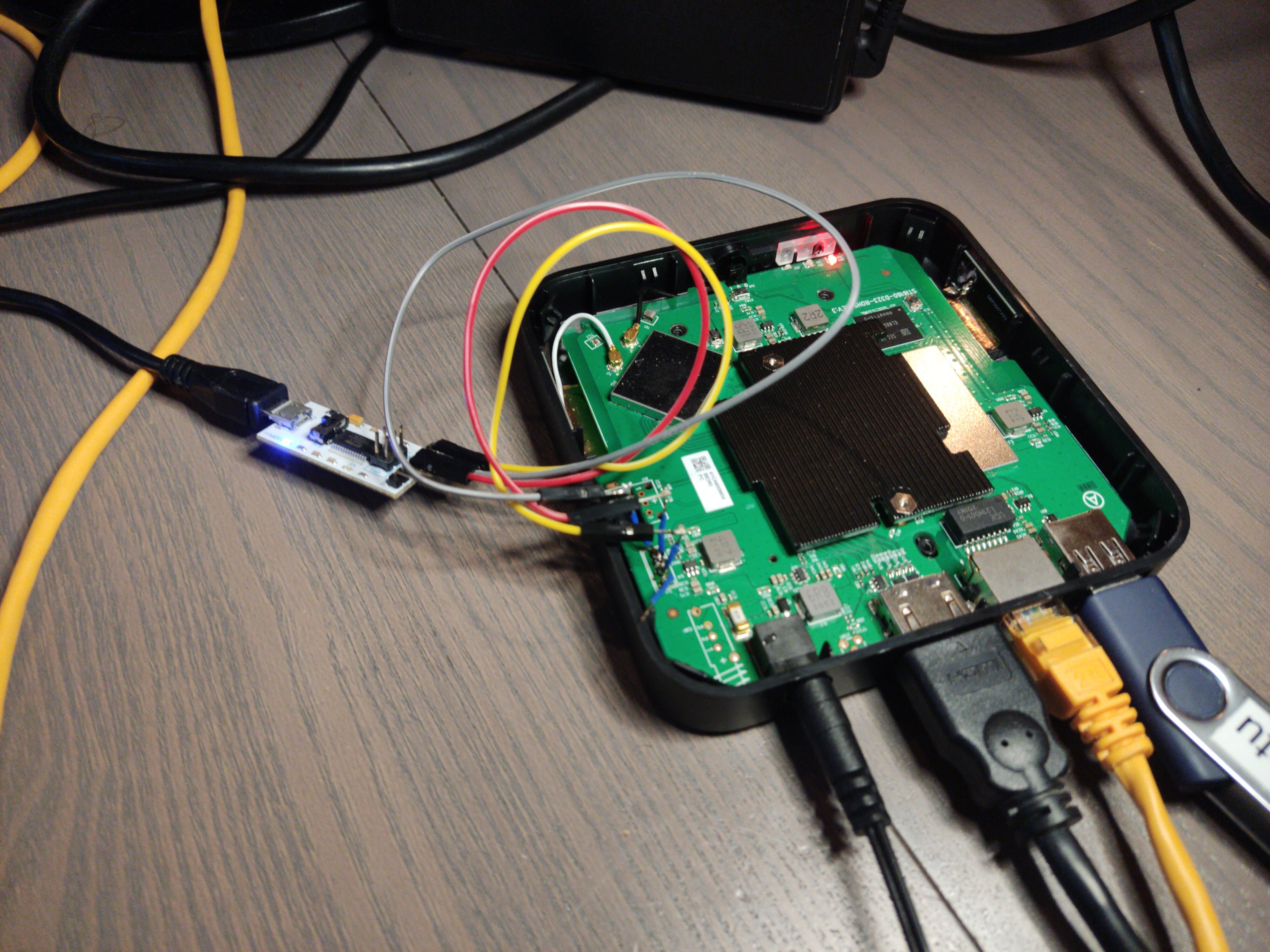
Using the multimeter in continuity mode, we identified which pin of the debug port was ground. Visual inspection showed that there was a ground pin, a power pin (VCC) and two IO pins connected to what we assumed to be the main CPU, pulled high with resistors connected to VCC.
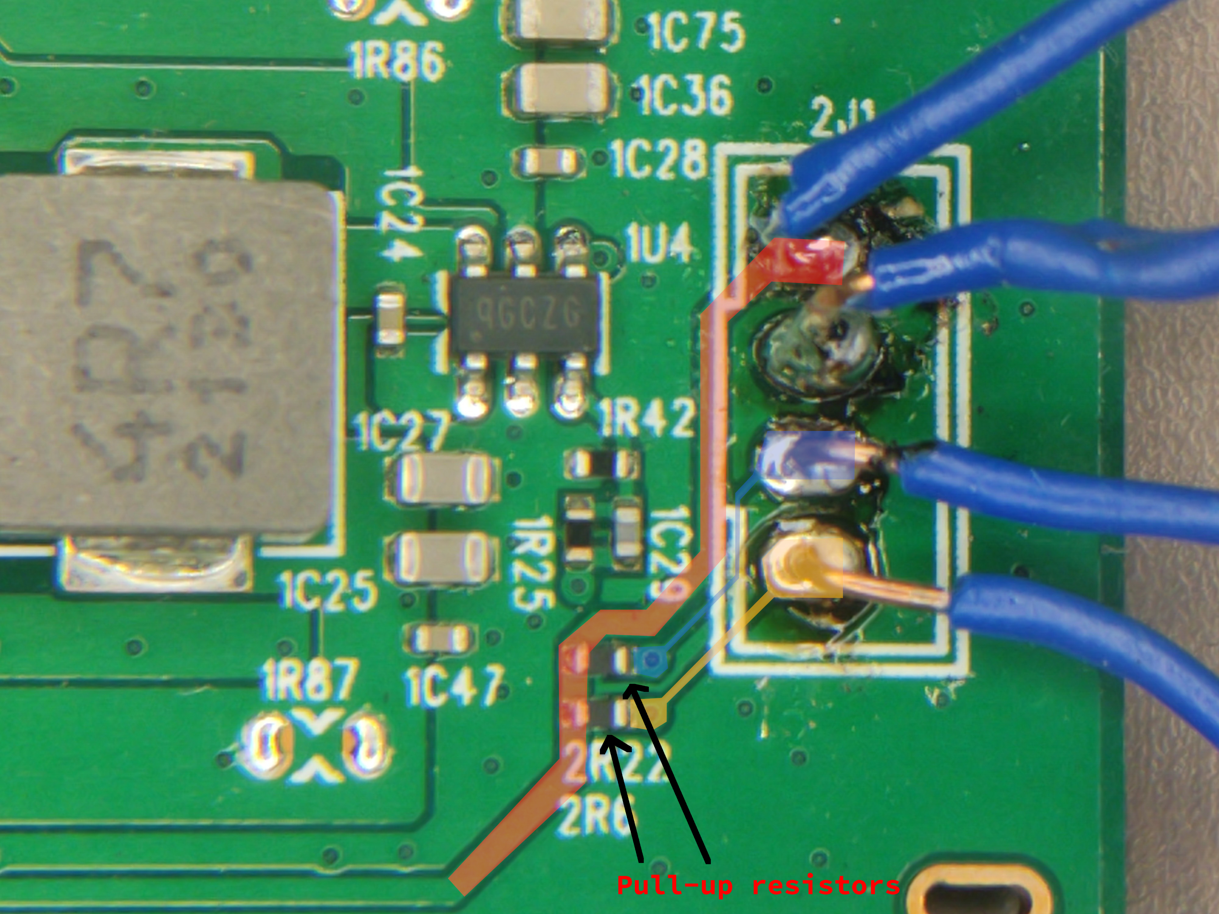
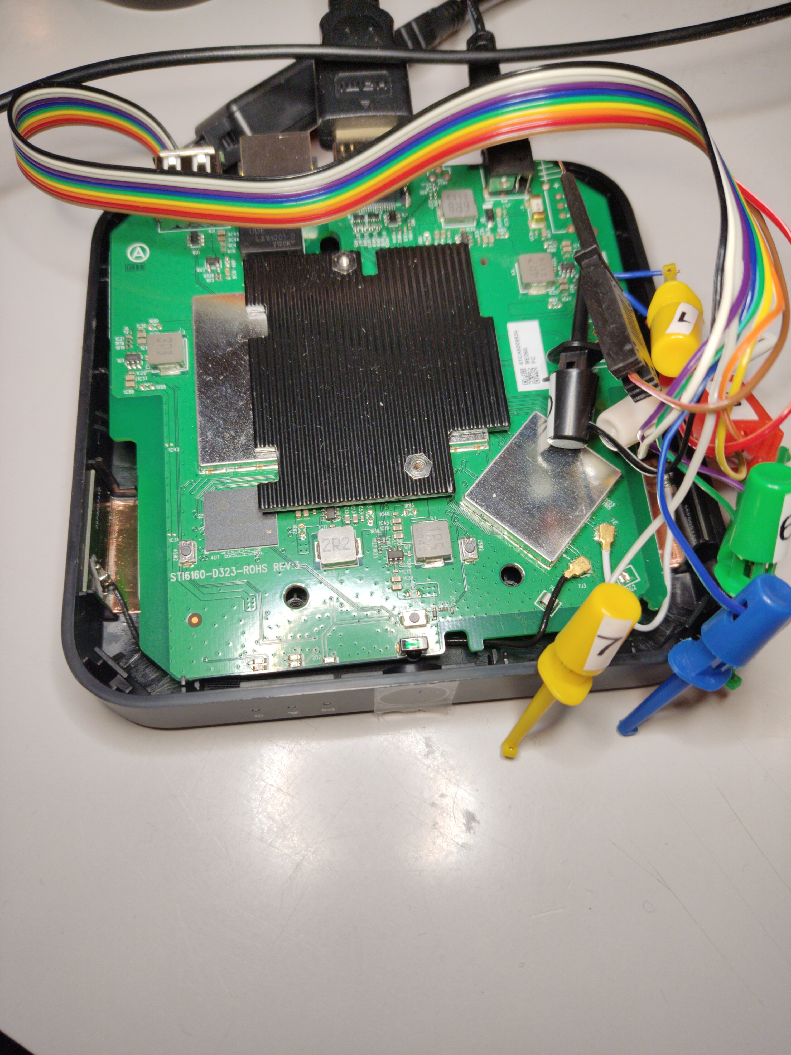
We then soldered wires (it’s not pretty or clean, but it works) to the port and used a cheap logic analyser to see what is happening on the IO pins (a logic analyser is a tool that captures and displays multiple signals from a digital device). See the screenshot below for what happens after booting the device.
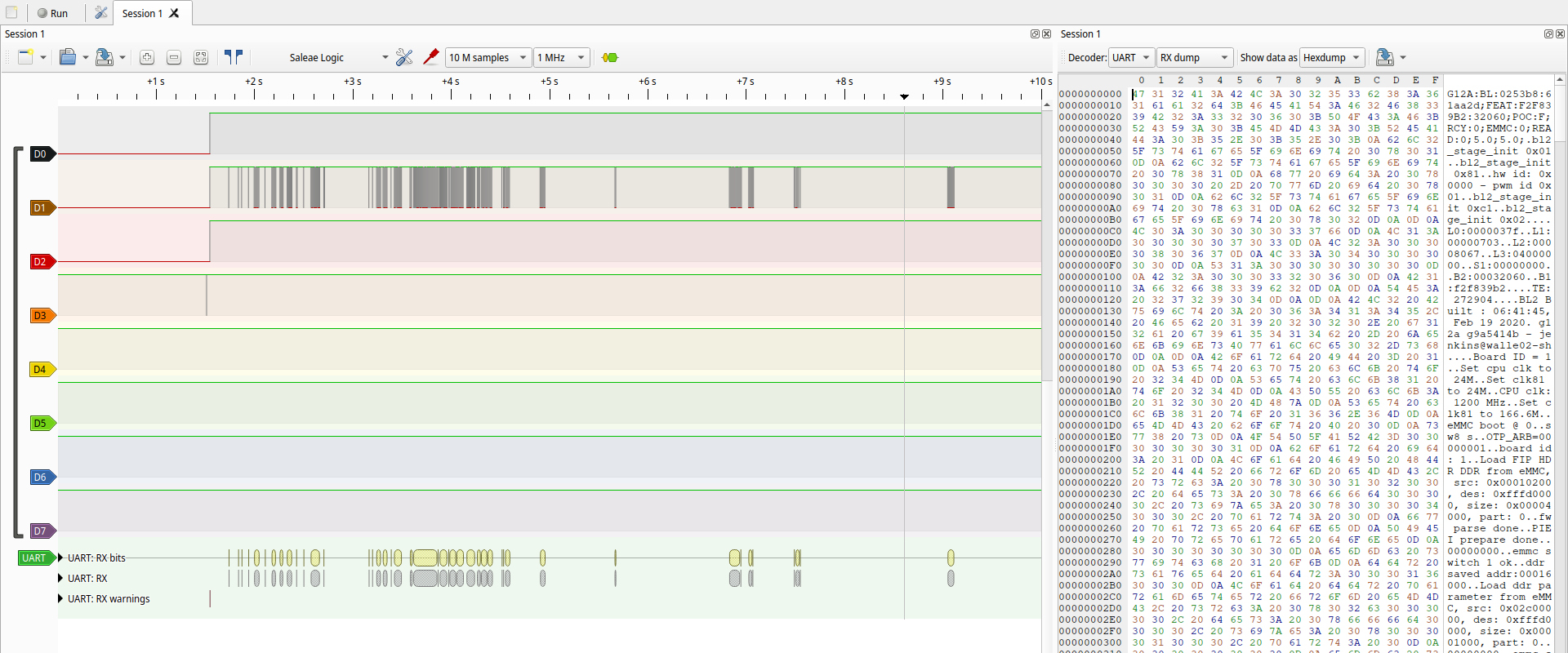
On the screenshot, you can see that there is one pin that’s constantly high (because of the resistor between it and VCC), and one pin where there are signals. These signals look like serial, so we used the serial protocol decoder to decode the signal, and indeed, it is serial at 115200 baud. From this, it follows that the other pin is probably the RX (receive) pin: it’s constantly high because we don’t send anything yet.
We detached the logic analyser from the device and then connected a USB to serial adapter, taking care of connecting the TX of the adapter to RX on the board and vice versa. We were also careful to get the voltage right by setting the switch on the adaptor to 3.3V (it would be very sad to accidentally blow up the debug port).
Letting the device boot resulted in a lot of text being printed to the serial console, from which we’ll show a small part:
G12A:BL:0253b8:61aa2d;FEAT:F2F839B2:32060;POC:F;RCY:0;EMMC:0;READ:0;5.0;5.0;
...
BL2 Built : 06:41:45, Feb 19 2020. g12a g9a5414b - jenkins@walle02-sh
...
LPDDR4_PHY_V_0_1_21-Built : 20:05:08, Jan 10 2020. g12a g3576a48 - zhiguang.ouyang@droid07-sz
...
[Image: g12a_v1.1.3482-c90792be1 2020-06-12 19:52:03 wencai.you@droid11-sz]
...
U-Boot 2015.01 (Sep 09 2021 - 15:53:17)
...
Filesystem: FAT12 "KEYBOX PART"
gpio: pin GPIOAO_3 (gpio 3) value is 1
Command: bcb uboot-command
Start read misc partition datas!
BCB hasn't any datas,exit!
s_version: U-Boot 2015.01
amlkey_init() enter!
amlkey_init() 71: already init!
[EFUSE_MSG]keynum is 4
[KM]Error:f[key_manage_query_size]L515:key[oemkey] not programed yet
Interface:  MMC
  Device 1: Vendor: Man 000015 Snr 4baa48a1 Rev: 0.6 Prod: 8GTF4R
            Type: Removable Hard Disk
            Capacity: 7456.0 MB = 7.2 GB (15269888 x 512)
Filesystem: FAT12 "KEYBOX PART"
Hit Enter or space or Ctrl+C key to stop autoboot -- :  0
pll tsensor avg: 0x1dfe, u_efuse: 0x64
temp1: 24
ddr tsensor avg: 0x1e10, u_efuse: 0x50
temp2: 24
device cool done
...
This boot log contains a ton of information: build dates, usernames and hostnames of developers’ computers, but, most importantly, the line Hit Enter or space or Ctrl+C key to stop autoboot -- : 0. Spamming Enter when the device was booting did indeed stop the autoboot, and dropped us into a kind of shell:
Filesystem: FAT12 "KEYBOX PART"
Hit Enter or space or Ctrl+C key to stop autoboot -- :  0
g12a_u212_v1#
g12a_u212_v1#
g12a_u212_v1#
g12a_u212_v1#help
?       - alias for 'help'
aml_sysrecovery- Burning with amlogic format package from partition sysrecovery
amlmmc  - AMLMMC sub system
amlnf   - aml mtd nand sub-system
autoscr - run script from memory
...
it became clear that this was uBoot, a popular open-source bootloader. uBoot is almost never included in hardware without modifications from the hardware vendor, so it’s useful to check the version and other information:
g12a_u212_v1#version

U-Boot 2015.01 (Sep 09 2021 - 15:53:17)
aarch64-none-elf-gcc (crosstool-NG linaro-1.13.1-4.8-2013.11 - Linaro GCC 2013.10) 4.8.3 20131111 (prerelease)
GNU ld (crosstool-NG linaro-1.13.1-4.8-2013.11 - Linaro GCC 2013.10) 2.23.2.20130610 Linaro 2013.10-4
The next task we’d like to accomplish, is to take a dump of the eMMC memory. There is a mmc command in uBoot, which can (among other things) do the following:
g12a_u212_v1#mmc help
mmc - MMC sub system

Usage:
mmc info - display info of the current MMC device
mmc read addr blk# cnt
mmc write addr blk# cnt
We used the mmc read subcommand, which takes a memory address to put the data in, a block-number from where it will start, and an amount of blocks to read. After the data is read into memory, we need to get it out. We first tried the md.b command (memory display bytes). This command takes an address and amount of bytes, and prints those out to the serial console as a hexdump. This process can be automated with a Python script to read out the entire 8GB eMMC storage chip. Unfortunately, this approach proved to be too slow to use: a back-of-the napkin calculation showed that it would take around 49 days to completely transfer all the memory.
Luckily, another command was found: fatwrite. This will write memory to a file on a FAT filesystem. The box also has a USB port, where a memory stick can be plugged into. Using a combination of mmc read and fatwrite, we started dumping the eMMC chip. This once again proved to be rather slow and would take ~4 days. The fatwrite command was replaced with usb write, which removed the overhead of the filesystem and directly dumped the data to the disk, byte for byte exactly the same as the eMMC partition.
With a backup of the eMMC in hand, we can confidently move on to try to run Linux on the box. Inspecting the eMMC dump, showed that the board is a U212 reference design board, with an Amlogic S905X2 Quad-Core ARM Cortex-A53 SoC.
Looking up this chip, we found the amlogic-s9xxx-armbian repository on GitHub. This Armbian version is specifically made for the chip on our device; we’re in luck that someone has already gone through the effort of building this. Armbian is a Debian-based distro specifically for ARM chips (ARM here refers to the instruction set of the CPU; on most laptops, this instruction set is x86).
Getting this to work was once again a path littered with many dead-ends. A crucial piece of information was this blogpost by 7Ji that describes how the bootflow on Amlogic devices works. It became clear that we wouldn’t be able to directly boot Linux from the bootloader that was shipped on the device, but that we would first need to boot into a bootloader we control before booting Linux (this to get rid of the weird vendor-specific configuration/code). This practice is called chainloading. We used one of the bootloaders that ships with the Armbian version for the S905X2 chip.
We chainloaded by first loading the bootloader into memory, and then jumping to it.
g12a_u212_v1#fatload usb 0:1 0x1000000 u-boot-s905x2-s922.bin
740080 bytes read in 104 ms (6.8 MiB/s)
g12a_u212_v1#go 0x1000000
## Starting application at 0x01000000 ...


U-Boot 2015.01-dirty (Aug 14 2020 - 19:56:34)

DRAM:  2 GiB
Relocation Offset is: 76eec000
...
odroidn2#
This starts the second bootloader and drops us into another shell (with odroid2 as the shell prompt, which is another single-board-computer). From here, we want to boot into Linux. For this, we need four things:
- The Linux kernel
- A very simple filesystem object called INITRD (Inital RAM Disk). This contains the initial files needed to continue the booting process
- Arguments for the kernel. These are pretty standard.
- An FDT file (Flattened device tree). This file describes the hardware and is used by the Linux kernel to load drivers and configure the hardware.
The first two are provided by the Armbian project, but the FDT is board-specific and didn’t seem to be available yet for mainline Linux: we did dump the eMMC storage and find a Device Tree Blob, but this is Android-specific. The Linux kernel used by the Android TV version in the device was forked from mainline to include support for the hardware. Those changes were not mainlined (brought into Linus Torvalds’ version) by the hardware vendor, but by other developers, causing the Android DTB and mainline Linux DTB to not be compatible.
We used a quick and dirty hack to fix this: trying different device tree blobs for other, similar boards, until the device boots and has the necessary hardware support. In the end, we used the meson-g12a-sei510.dtb blob. Booting then happened like this:
fatload usb 0:1 0x11000000 uEnv.txt
env import -t   0x11000000
fatload usb 0:1 0x10000000 ${FDT}
fatload usb 0:1 0x11000000 ${LINUX}
fatload usb 0:1 0x13000000 ${INITRD}
setenv bootargs ${APPEND}
booti 0x11000000 0x13000000 0x10000000
with the content of uEnv.txt:
LINUX=/zImage
INITRD=/uInitrd
FDT=/dtb/amlogic/meson-g12a-sei510.dtb
APPEND=root=UUID=26bc1f8b-a9c1-4f86-91a9-c6c2b529f402 rootflags=data=writeback rw rootfstype=ext4 console=ttyAML0,115200n8 console=tty0 no_console_suspend consoleblank=0 fsck.fix=yes fsck.repair=yes net.ifnames=0 cgroup_enable=cpuset cgroup_memory=1 cgroup_enable=memory swapaccount=1
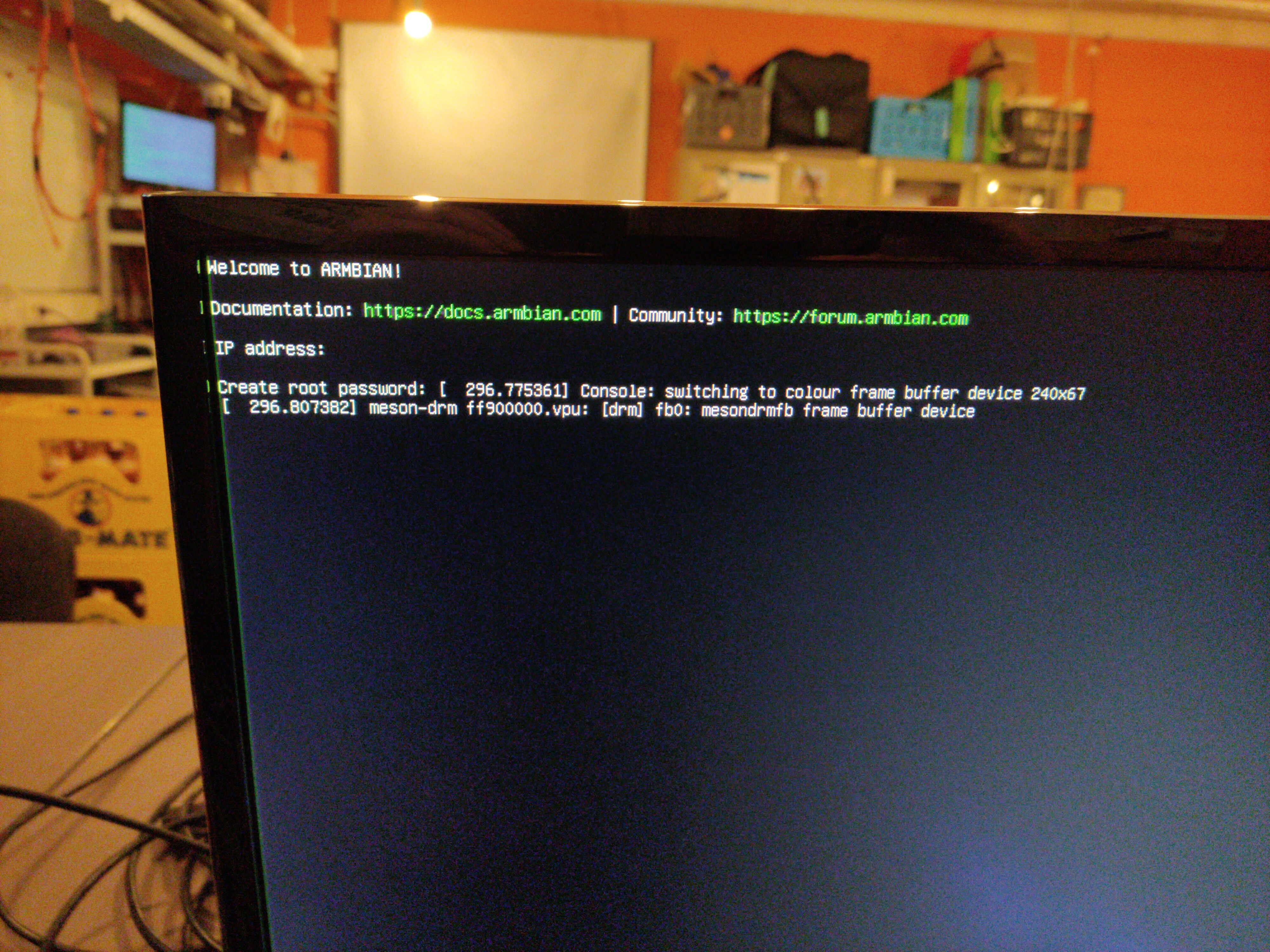
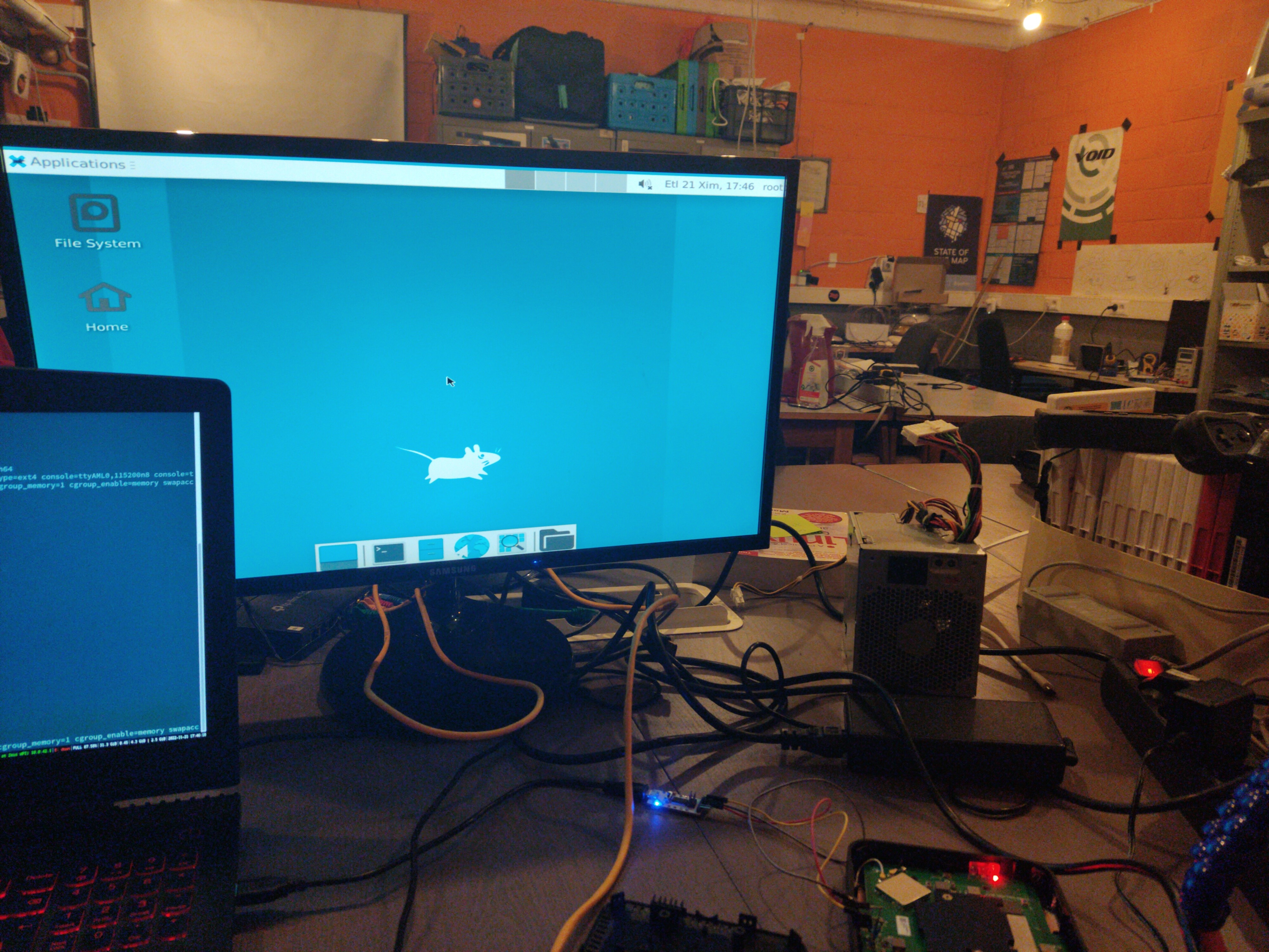
This booted us into a working Linux shell, with both Ethernet and HDMI working! We were even able to install XFCE to get a graphical shell.
We didn’t get the onboard Wi-Fi chipset to work yet, but that’s fine since this box will most probably be used with Ethernet anyway.
One final piece of work that remained was automatically booting into Linux when the USB stick was inserted: at the moment, booting into Linux takes first booting a secondary bootloader, then starting the kernel. This both happened interactively on the serial console, which is annoying because then we can’t close the box back up again.
To automatically boot into the secondary bootloader, we modified the environment variables that are written on the eMMC storage; this is the only write we did to the eMMC storage. Originally, the bootcmd environment variable contained run storeboot, which starts the Android boot process:
g12a_u212_v1#defenv
g12a_u212_v1#setenv bootcmd 'usb start && if fatload usb 0:1 0x1000000 u-boot-s905x2-s922.bin; then go 0x1000000; else run storeboot; fi'
g12a_u212_v1#saveenv
reboot
This now boots the secondary bootloader automatically if possible. From here, we tried to use an extlinux config file to automatically boot Linux; extlinux.conf has a very simple config format where you specify the kernel, initramfs, arguments and the device tree; the bootloader then does the rest of the work booting the device.
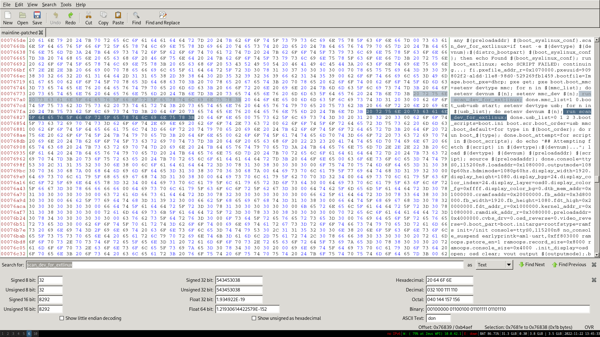
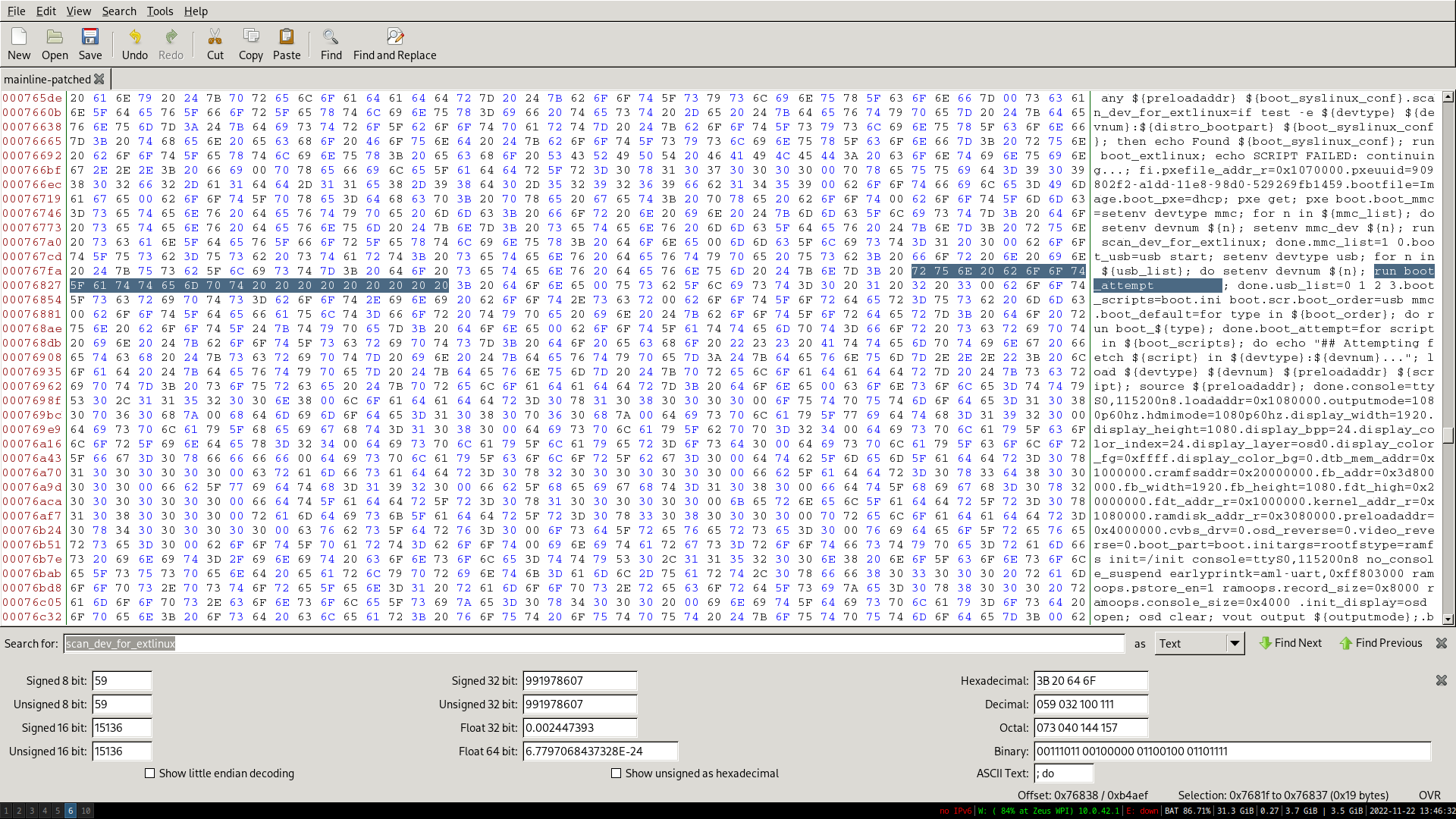
Unfortunately, due to a bug in the secondary bootloader, the extlinux config handler seemed to be broken, so automatically booting didn’t work there. We also didn’t find a way of passing commands from the first bootloader to the second one. 7Ji’s blogpost about the bootloader mentioned that if there is a file called boot.scr or aml_autoscript on the USB memory stick, it would be automatically executed. This proved to be false: there is indeed a boot_attempt command that executes these scripts on any storage it can find, but it’s not executed by the bootcmd.
We didn’t want to have to recompile the bootloader, so we patched it with a hexeditor. The new command is shorter than the old command, so we filled the rest with spaces.
We’ve now reached all our goals: the set-top box automatically boots into Linux, with support for Ethernet and HDMI. The original Android install still boots when the special USB stick is not inserted.
If you have questions or some things are not clear, feel free to contact me: zeusblog@notdevreker.be